Hydrostatic forces are the resultant force caused by the pressure loading of a liquid acting on submerged surfaces. Calculation of the hydrostatic force and the location of the center of pressure are fundamental subjects in fluid mechanics. The center of pressure is a point on the immersed surface at which the resultant hydrostatic pressure force acts.
The location and magnitude of water pressure force acting on water-control structures, such as dams, levees, and gates, are very important to their structural design. Hydrostatic force and its line of action is also required for the design of many parts of hydraulic equipment.
The objectives of this experiment are twofold:
In this experiment, the hydrostatic force and center of pressure acting on a vertical surface will be determined by increasing the water depth in the apparatus water tank and by reaching an equilibrium condition between the moments acting on the balance arm of the test apparatus. The forces which create these moments are the weight applied to the balance arm and the hydrostatic force on the vertical surface.
Equipment required to carry out this experiment is the following:
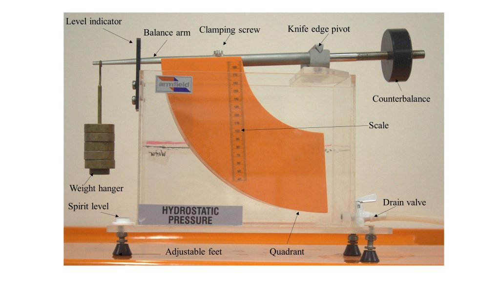
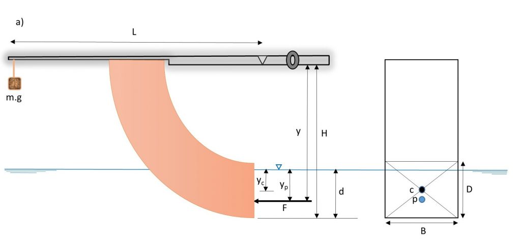
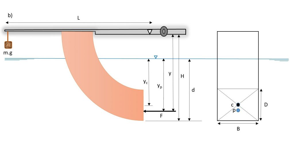
The equipment is comprised of a rectangular transparent water tank, a fabricated quadrant, a balance arm, an adjustable counter-balance weight, and a water-level measuring device (Figure 1.1).
The water tank has a drain valve at one end and three adjustable screwed-in feet on its base for leveling the apparatus. The quadrant is mounted on a balance arm that pivots on knife edges. The knife edges coincide with the center of the arc of the quadrant; therefore, the only hydrostatic force acting on the vertical surface of the quadrant creates moment about the pivot point. This moment can be counterbalanced by adding weight to the weight hanger, which is located at the left end of the balance arm, at a fixed distance from the pivot. Since the line of actions of hydrostatic forces applied on the curved surfaces passes through the pivot point, the forces have no effect on the moment. The hydrostatic force and its line of action (center of pressure) can be determined for different water depths, with the quadrant’s vertical face either partially or fully submerged.
A level indicator attached to the side of the tank shows when the balance arm is horizontal. Water is admitted to the top of the tank by a flexible tube and may be drained through a cock in the side of the tank. The water level is indicated on a scale on the side of the quadrant [1].
In this experiment, when the quadrant is immersed by adding water to the tank, the hydrostatic force applied to the vertical surface of the quadrant can be determined by considering the following [1]:

m : mass on the weight hanger,
L : length of the balance arm (Figure 1.2)
F : Hydrostatic force, and
y : distance between the pivot and the center of pressure (Figure 1.2).
Then, calculated hydrostatic force and center of pressure on the vertical face of the quadrant can be compared with the experimental results.
The magnitude of the resultant hydrostatic force (F) applied to an immersed surface is given by:

Pc : pressure at centroid of the immersed surface,
A: area of the immersed surface,
yc : centroid of the immersed surface measured from the water surface,
: density of fluid, and
g : acceleration due to gravity.
The hydrostatic force acting on the vertical face of the quadrant can be calculated as:
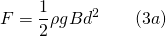
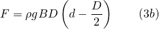
B : width of the quadrant face,
d : depth of water from the base of the quadrant, and
D : height of the quadrant face.
The center of pressure is calculated as:
is the 2 nd moment of area of immersed body about an axis in the free surface. By use of the parallel axes theorem:
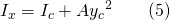
where is the depth of the centroid of the immersed surface, and is the 2 nd moment of area of immersed body about the centroidal axis. is calculated as:
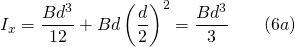
![\displaystyle I_x=BD \left[ \frac{D^2}{12}+\left(d-\frac{D}{2}\right)^2 \right] \qquad (6b)](https://uta.pressbooks.pub/app/uploads/quicklatex/quicklatex.com-ce7a60a5a8f0600ec1c0f748d233db58_l3.png)
The depth of the center of pressure below the pivot point is given by:
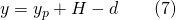
in which H is the vertical distance between the pivot and the base of the quadrant.
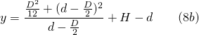
Substitution of Equation (6a and 6b) and into (4) and then into (7) yields the theoretical results, as follows:

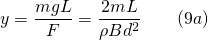
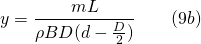
For equilibrium of the experimental apparatus, moments about the pivot are given by Equation (1). By substitution of the derived hydrostatic force, F from Equation (3a and b), we have:
Begin the experiment by measuring the dimensions of the quadrant vertical endface (B and D) and the distances (H and L), and then perform the experiment by taking the following steps:
Please visit this link for accessing the excel workbook for this experiment.
Record the following dimensions:
All mass and water depth readings should be recorded in the Raw Data Table:
Depth of Immersion, d (m)
Calculate the following for the partially and fully submerged quadrants, and record them in the Result Table:
| Test No. | Mass m(kg) | Depth of immersion d(m) | Hydrostatic force F(N) | Theoretical depth of center of pressure (m) | Experimental depth of center of pressure (m) |
| 1 | |||||
| 2 | |||||
| 3 | |||||
| 4 | |||||
| 5 | |||||
| 6 | |||||
| 7 | |||||
| 8 | |||||
| 9 | |||||
| 10 |
Use the template provided to prepare your lab report for this experiment. Your report should include the following:
Applied Fluid Mechanics Lab Manual Copyright © 2019 by Habib Ahmari and Shah Md Imran Kabir is licensed under a Creative Commons Attribution 4.0 International License, except where otherwise noted.